
6-DOF Wire-Driven
Haptic Interface
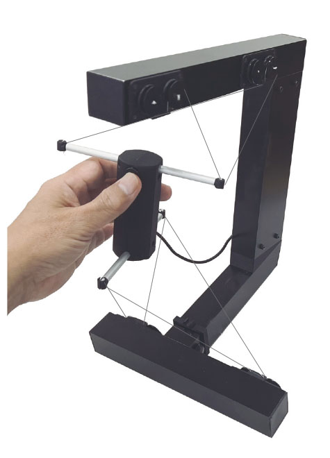
SPIDAR-GⅡ is a wire-driven 6-DOF high performance haptic display device.
The device is composed of wires, pulleys and DC motors.
These elements have a signficant reduction of the inertia because of their lightwaight proprieties,
compared to other architectures of haptic
devices. Built-in HC (Haptic Controller) with encoder counters, motor drivers and USB 2.0 interface enables prominent calculations at hardware
level. As a result, SPIDAR-GⅡ with HC realizes high performance with stable haptic sensations.
6-DOF Wire-Driven Haptic Interface
SPIDAR, which stands for
‘SPace Interface Device for Artificial Reality’, is a series of string-based
haptic interface device. Since its first version developed by Dr. Makoto SATO in 1989, SPIDAR has
emerged as a distinguished haptic interface capable of displaying various aspects of force feedback.
The usage of string-based technology to track user’s hands’ or fingers’ position as well as display
force feedback leaves the system with less weight, better scalability and better flexibility. Still, the
quality of SPIDAR’s haptic feedback continues improving through time to reach the current standard,
and in line with other major haptic systems, of accurate measurements and smooth force display.
1) Calculation of pointer’s current position and orientation vector,
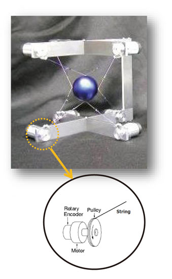
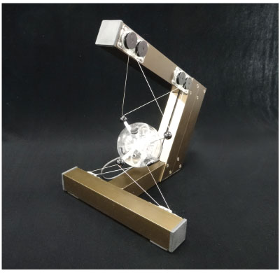
Among several versions of SPIDAR,
SPIDAR-G is a grip-type, tension- based 6-DOF haptic interface
with 8 strings and 8 driving motors.
As shown in the figure beside, for each string, one end is connected to the grip; the other end is
attached to the pulley settled around the axis of a DC motor.
For each driving motor, a rotary encoder is attached to measure the string’s length. With the current
encoder value vector

and the encoder value vector at the last clock cycle,

, the variation of string’s
length can be calculated by formula (1).
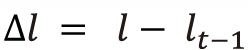 (1)
(1)
Then, while

stands for the pointer’s current position and orientation vector, difference between
and

, the pointer’s position and orientation vector at the last clock cycle,

can be approximately
calculated by solving formula (2). Here,
stands for the difference.
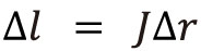 (2)
(2)
In formula (2),

stands for the Jacobian matrix which depends on
and
.
Once
is calculated, the present positionand orientation vector
is updated as formula (3).
 (3)
2) Distribution Calculation for actuator’s torque
(3)
2) Distribution Calculation for actuator’s torque
To reproduce forces with given magnitude and direction, distribution calculation based on quadratic
programming is performed to assign proper output torque to every single driving motor.
Resultant force of strings' tension acting upon the grip is supposed to be the same as the expected force.
Force display can be used to reproduce virtual object’s weight and material, state of motion,
as well as interaction forces between multiple virtual objects.
| Force Feedback |
6DOF x, y, z, Tx, Ty, Tz |
| Position Setting |
6DOF x, y, z, Roll, Pitch, Yaw |
| Workspace |
150(W) x 150(H) x 190(D) mm |
| Maximum Force |
2.0 N (Translation), 0.001 rad (Angle) |
| Motor |
DC Motor x 8 |
| Encoder |
512 pulse / turn |
| Frequency |
1 kHz |
| Interface |
USB 2.0 |
| OS |
Windows 7 / 10 |